

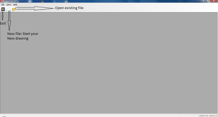
DIMENSIONS – a product outline
Procam DIMENSIONS is a Computer-Aided Design System based on Microsoft technology that was developed in cooperation with users, customers, and industry advisers to address the requirements of the leather manufacturing industry. Our teams more than 20 years of collective experience in the development of human-centered software solutions are concentrated in DIMENSIONS. The system can be operated as a stand-alone solution, or be integrated into an IT-network, build on off-the-shelf DB server.
DIMENSIONS! is the foundation of Procams software solutions for integrated product development. The CAD data and information contained within DIMENSIONS! are the basis for all further enterprise processes, such as cost calculation, material allocation, cutting, product data management, production planning, etc. Because of this, future-oriented technologies and open standards were a basic requirement during development.
DIMENSIONS – Benefits
- Reduced Development Periods
- Individual Working Routines
- Interactive 2D/3D Operation
- Database Connectivity
- Integration
- Native 64-bit software
DIMENSIONS – Key features
- Pattern Engineering System (CAD)
- Full 2D and 3D CAD integration
- 2D technical tool (engineering, grading, etc.)
- 3D virtual design tool (communication tool)
- Third-party integration (Adobe, Excel, etc.)
- Database Interfaces (Oracle®, MS-SQL®)
- Communication-based on standard HTTP
- Ray Tracing
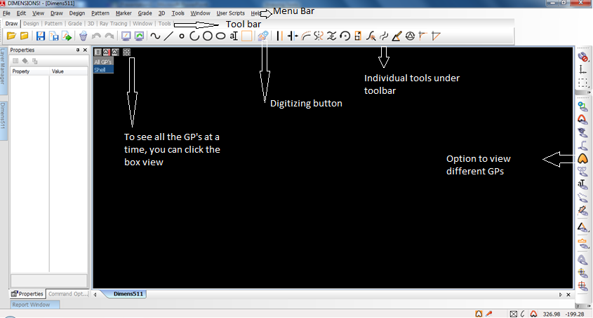
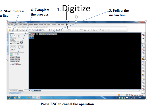
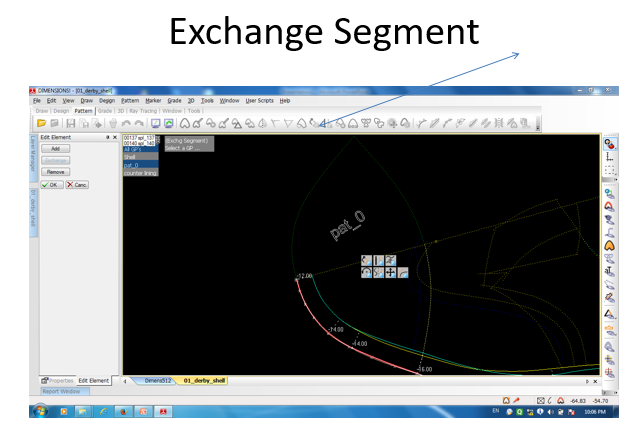
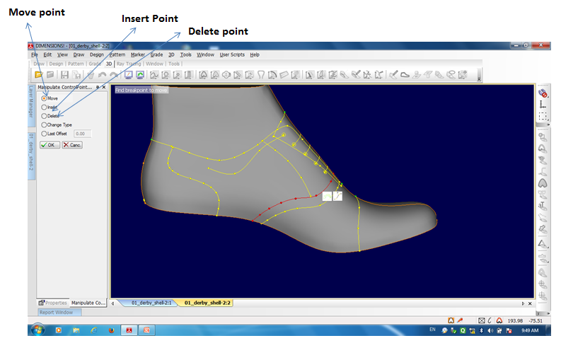
Digitizing buttons:
- Select spline
- –0 new point
- –1 corner point
- –2 end point
- –3 undo


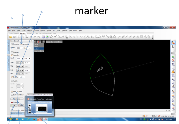
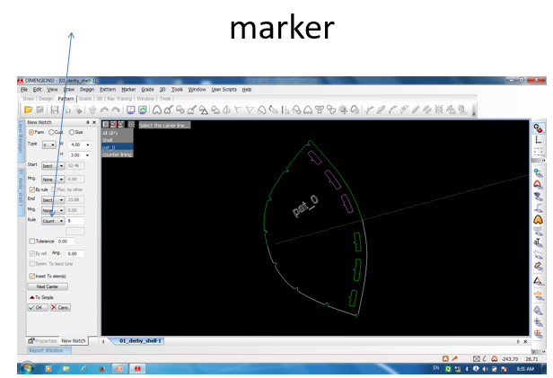
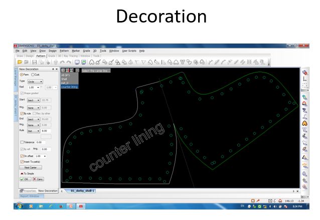
Marker:
- •Select the carrier line
- •Click to define the marker start position
- •Ctrl key to create marker on reverse side
- •Shift +ctrl key to make marker on both side
- •Finally press on
- •Next carrier to continue marker on other carrier line
Dimensions 3D:
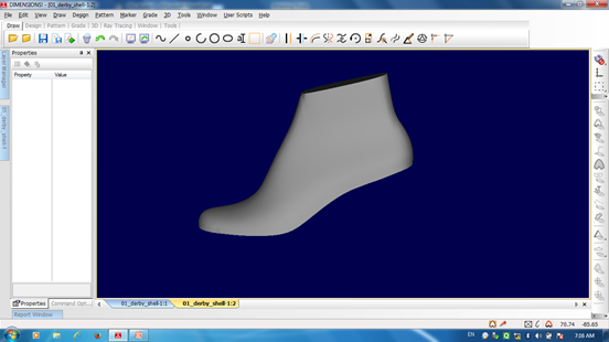
For doing something in dimension 3d, you first have to import the 3D last first. With the default software, they are providing two 3d Last with its package in ( ls5 ) format. Here you can import any of the last by .. File> import 3d last > choose last > ok. Thereafter you will see the 3 d last as given in Fig. You can move, pan, zoom and rotate last in the following way
- Hold right-click— to rotate the last.
- Hold Middle button– to move (pan) the last
- Rotate middle button – zoom the last
We can scan the last in 3d scanner thereafter by 3shape software we can convert that 3d last in ls5 format though several steps abd then import them in dimension software. But for scanning the 3d last, we need 3d scanner first. Previously 3d digitizer was used to digitize the 3d points of last to this software.
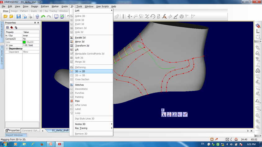
Now you can draw spline on the last by 3d> spline 3d option. And thereafter you can modify the line> create pattern. But as per my opinion, we can finalize the base of the same last in 2d and digitize the mainline > then move those lines in 3d.
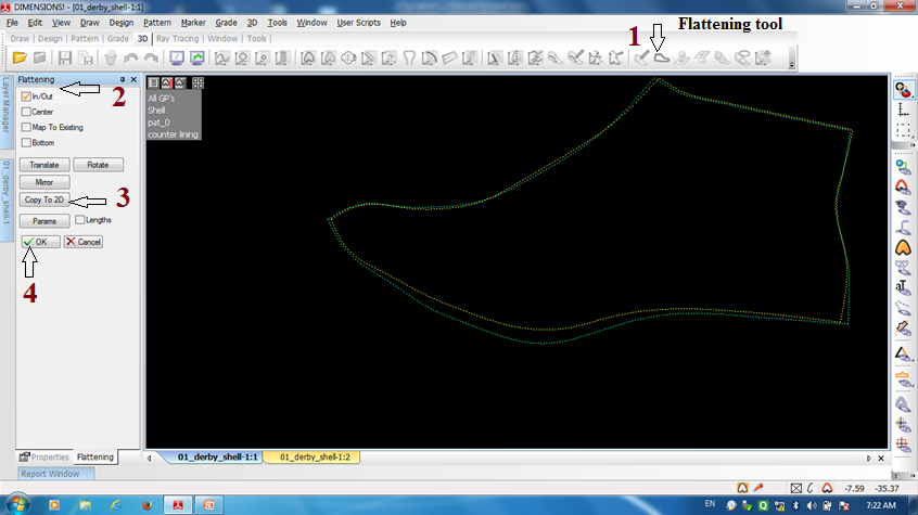
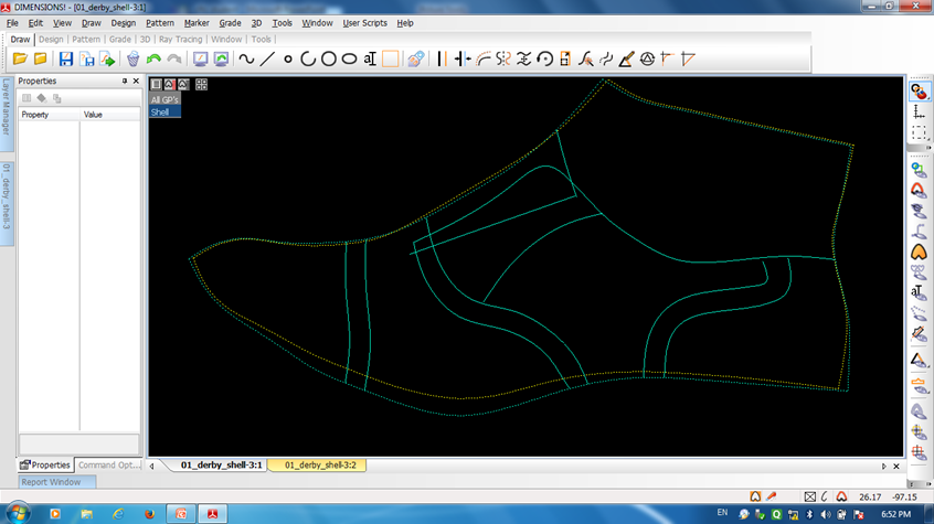
Here in the given picture (Fig ) we flatten 3d last on 2d. Steps are given by numbers in red marks.
Now we copy (Ctrl C) our 2d digitized pattern from 2d windows and paste (Ctrl V) it on flattening 2d windows, after that we will see the following figure.
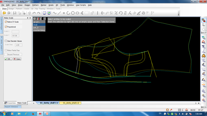
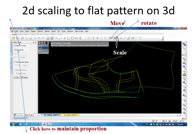
Now we need to resize our 2d pattern so that it can fit on 3d
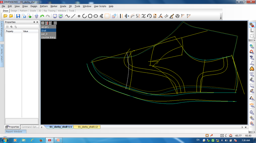
After finalizing the process, we will see the picture like the bottom one.
Now we have to select those lines which we want to transfer on 3d last .

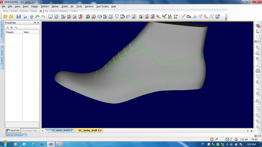
Now we can see those 2d lines on 3d as given below

Now we may need to modify some lines because when we want to transfer 2d to 3d line, some lines may be displaced.
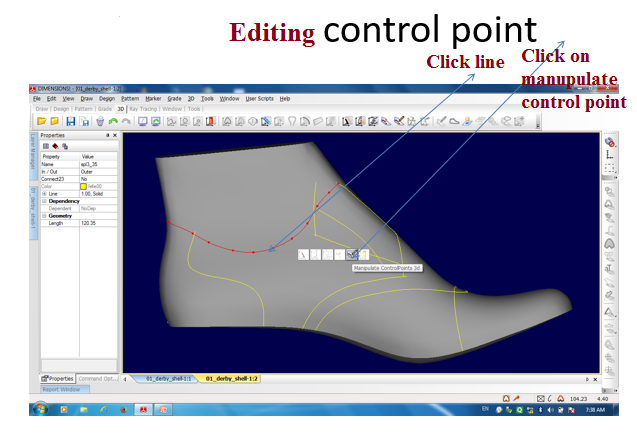
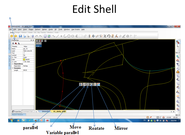
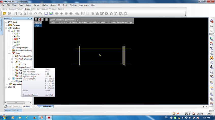
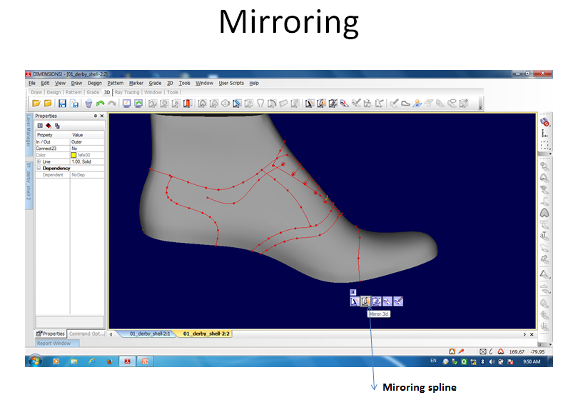
Dependency line: After mirroring we see two color line,
- Yellow line— editable
- Green line— dependent line (when you modify yellow line green line will be modified)
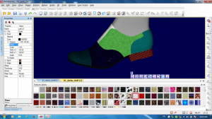
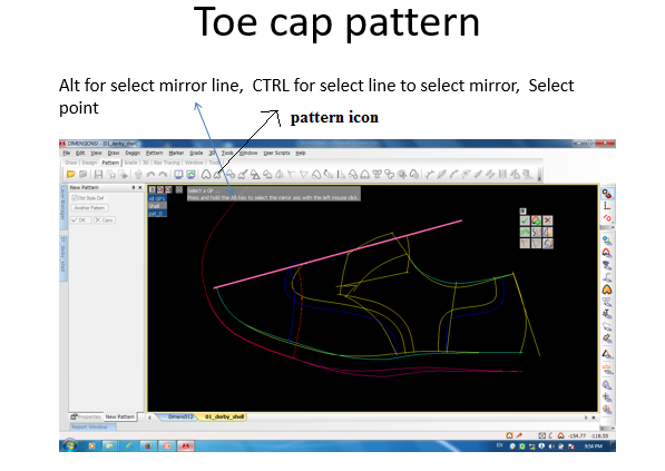
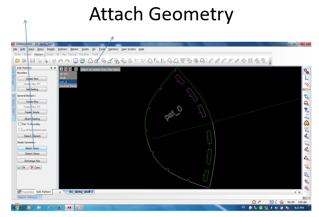
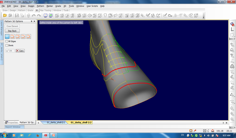
After editing of spline is complete, the pattern making process is started. Here in the pattern making process we select the boundary line in same directions till the mouse pointer is changed to drop icon. Then we have to click at any point within boundary. And pattern is created.
After making pattern we can change its color thickness texture by changing the pattern properties. Pattern can also be mirrored.
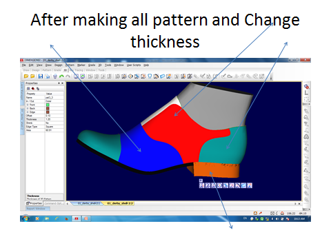

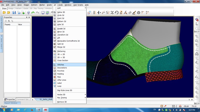
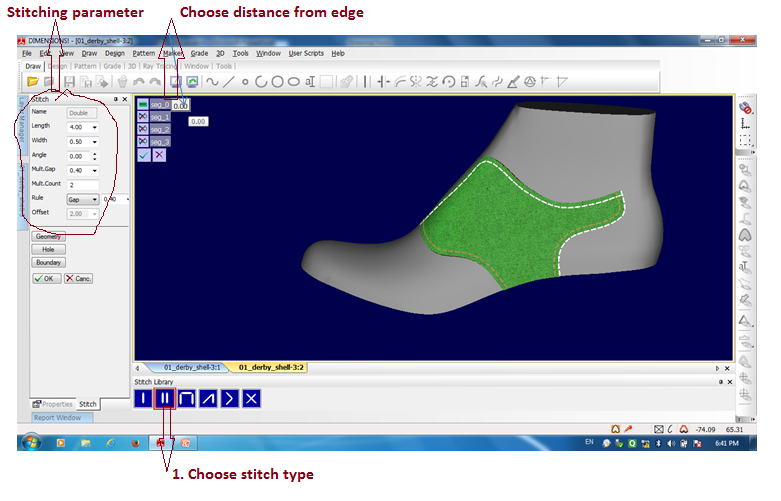
For making stitchline , select the 3d pattern>select the 3d stitch option from the drop down menu> select the stitch type> select distance from the edge >0k
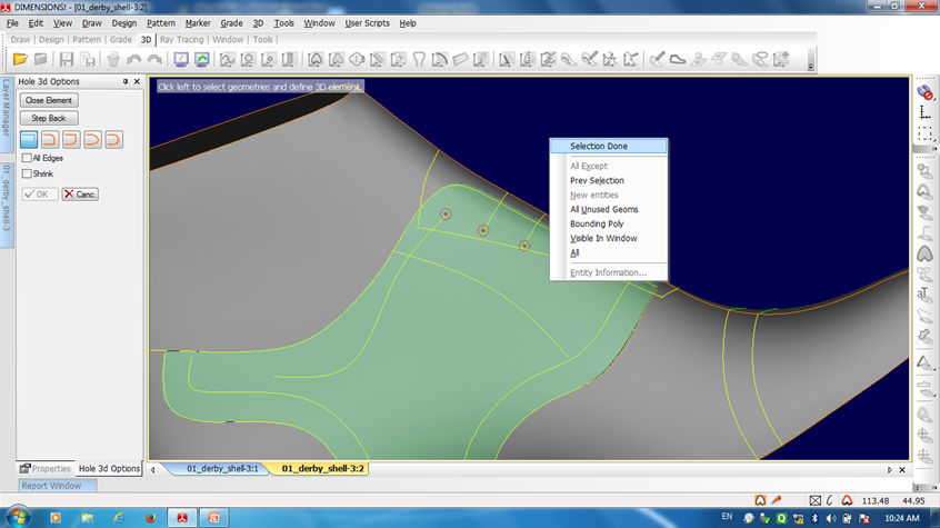
Eyeleting: For eyeleting we have draw 3d circle first and place them in the proper area. Then 3d pattern > hole 3d> select pattern> select the 3d circles > double click in outside area.
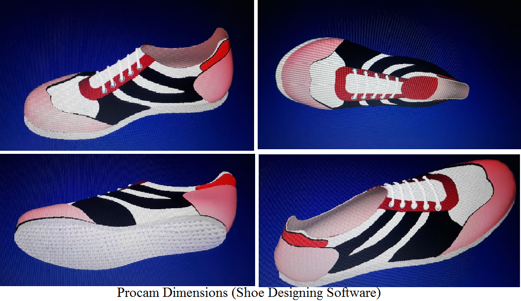
3D Design Example
Building Punches and Eyelets for Laces :
As you need a spline carrying the eylets it is a good time now to draw this line. Start and end the line at the position where the first and last eyelet should be placed later on. Next, use the punches function to place the holes where the eyelets should later be placed. If you use punches the design looks more realistic as a hole is located underneath the eyelet. Use the number of functions to define how many punches should be placed. Use the size parameter to set the punch size in order to fit your eyelet size.
Next, use the decoration function to place the eyelets on the same spline and using the same number as the punches before. Use the size parameter to set the eyelet to the size you need. The metallic effect parameter can be used in order to decide if the eyelet should have a shinning or matt surface.

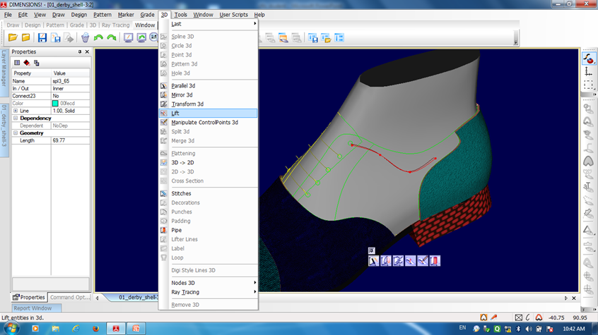
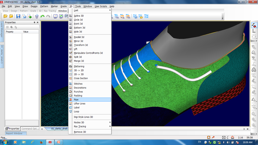
Lacing: For making shoe lace, we have to draw 3d spline in the lace area. Then select the spline >choose lift option >ok . Then select lifted spline again > choose pipe> select pipe diameter>select one end point of spline> select other end of the spline > ok. Now piping is ready. Now you can the colour and texture of the pipe in the same way as changing the pattern material.
3D Tubes / Laces
Use the Pipe function to apply tubes on the splines to make up the laces. You can use a smaller tube at the start and end of the laces to make it look even more realistic. You can choose between 3 shapes of Laces in the pipe menu. It is also possible to change the scale factor for the x and y-axis. With the Proportional switch, you are able to build proportional laces! If On whole carrier is checked the 3D Tube will be drawn over the hole selected carrier.
Setting end type: To set the end type for a tube or pipe, while the command is active click on the icon for the end type you want and then move the “shutter” slider to set the size of the pipe end.
3D Pattern Padding
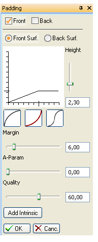
How to use the Padding Function
To be able to use the padding function, we have to create a pattern. First, we draw a 3D spline like in our picture to the right. Then we mirror the 3D spline over the Heel with the Mirror 3D function. Now we create a pattern with the Create 3D Pattern function. The result will look like this. Now let’s click on the Padding function button located on the 3D menu. Select the pattern we just created. D! will do a precalculation of the outcome.(dependent how strong your CPU is, it will take a moment). On the left side of the screen, the Padding properties will pop up, where you are able to adjust the padding for the pattern.
3D Place logo
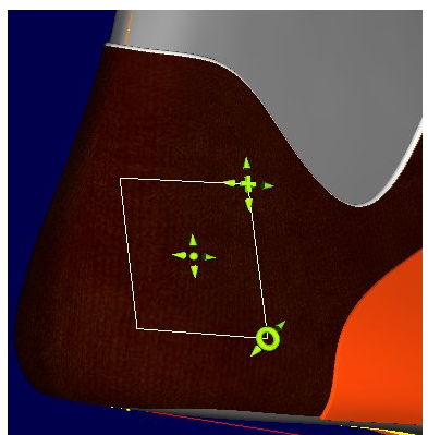
Start the command either from the 3D button bar or from the 3D drop-down menu. Select a BMP or jpg file to use as a logo, Click on a pattern you wish to place the logo on and a box defining the size of the logo is drawn, On the box there are positioning icons which allow you to move, rotate and scale the logo, click on the point in the center to move the logo, the circle to rotate and the cross in the corner of the logo to scale. Finally, to end the command and place the logo, double click left.
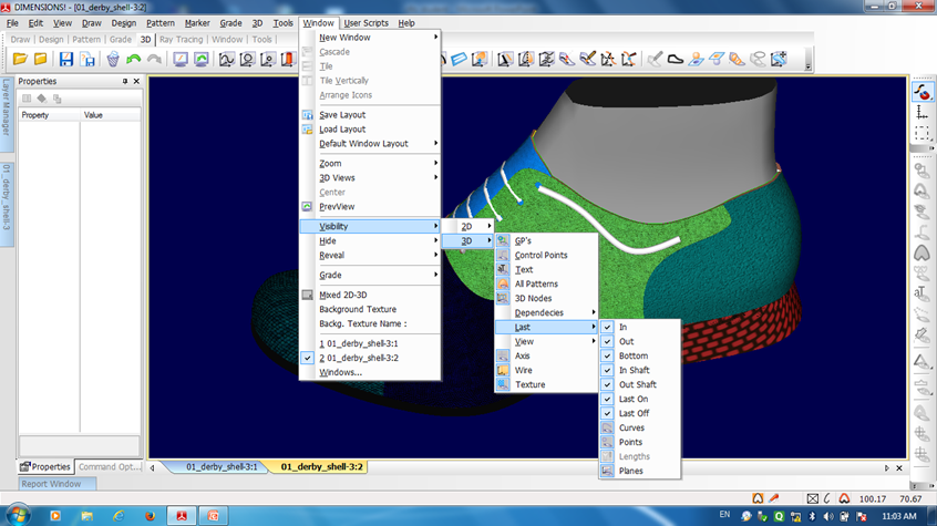
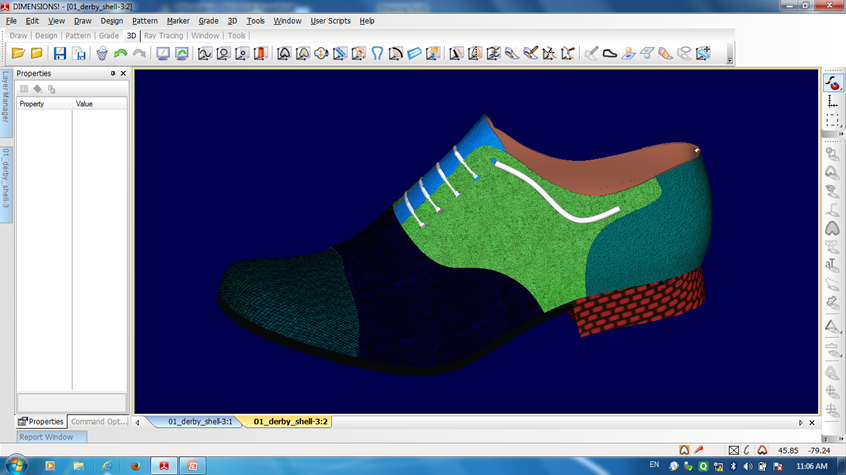
After completing the 3d upper and sole we can hide the unwanted material like last points etc by modifying visibility as given in figure
After finalizing the shoe if we want to make it, then we have to convert the 3d lines to 2d, which is done in the following process as given in figure
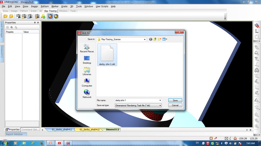
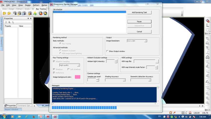
Export ray tracing, Rendering: In this process we can add differnt colour light source and different 3d stand to visualize the shoe in different environmental conditions as given in fig
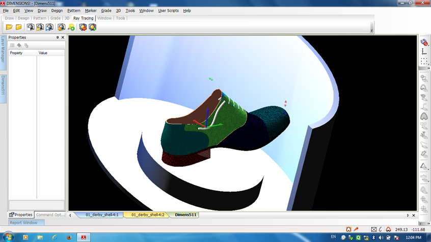
Ray-Tracing
Ray-Tracing is a method to calculate foto-realistic images from 3D synthetic data. Each ray-tracing image is a still picture of a given scene from a given view perspective and a given light situation. D! V_5.1 has an optional ray-tracing module that is used to create such high-quality 3D images from the 3D designs made in D!.
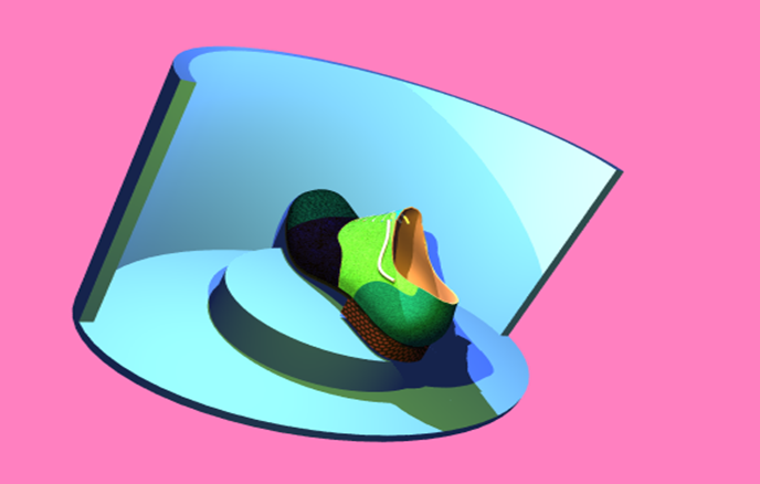
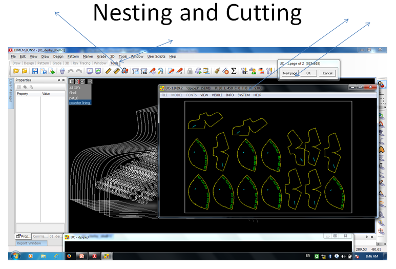
So in 3D, we can visualize the shoe without making it. Thus we make 3d prototype of shoes with different materials and send it to the buyer for approval. After finalizing the material we make the physical shoe. We can transfer the style line to other shoemaking software like Crispin, Shoemaster etc with the help of a universal converter (U.C) supplied by program.
After using different software, this author personally feels, getup or appearance of different shoe designing software are different but the sequence and process are almost the same. If any students can know any shoe designing software clearly, then he or she can handle other shoe designing software with the help of a few hours of training.
Reference:
- Dimensions tutorial …Procam
- CFTC class note
Please share your feedback and suggestions. In case if you have any queries about any topic of Footwear and Leather Goods, post it in the comment section. And if you like this topic you may share it on facebook, twitter or any social site. Thank you.
Hai sir,
It is very useful to the Bigginers. Who have entered in the field. And this is the best explanation about procam procedure.