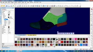


Teseo Naxos is a shoe designing software made by Teseo Italy. Here in the same platform, we can make digitizing, pattern making, grading, plotting, 3d Visualization, costing and product specification sheet. Here in this Naxos tutorial, we will discuss the process to adjust the digitized entity. The digitization part has already been discussed in the previous tutorials. Other parts will be discussed in follow on tutorials.
After digitizing, all perimeters, marks , pen, punch 1, punch 2 are all digitized entities. So in the time of digitizing, there may have some problems in digitizing entities or we need to adjust some digitized entity as per buyer request. So we need to modify it.
How to adjust/Modify the digitized entity?
To delete the irregularity of a digitized entity or to obtain the required curve just reposition the inserted knots.
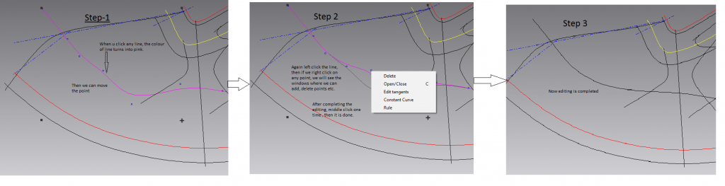
- Select the digitized entity to adjust;
- Click on the digitized entity again to enter the editing mode: the cursor appears with this shape ;
- Place the cursor at the required point and holding the selection key down, drag the digitized entity until the required modification is obtained. During this operation, it is possible to control the status toolbar the effective displacement.
How to insert a knot
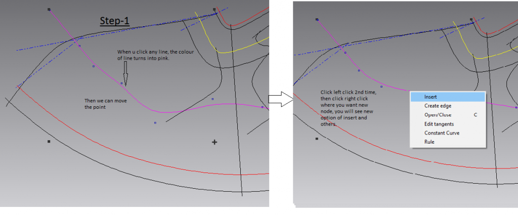
- Select the digitized entity to adjust.
- Click on the digitized entity again to enter the editing mode, the cursor appears with this shape.
- Place the cursor on the point of the digitized entity where another knot is required.
- Click the menu key and select Insert.
- Repeat the operation to insert other knots.
- Quit the function with the special key.
The “Insert knots” function considers the digitized entity type of the selected entity. If the line is “Broken line” type, by inserting another knot, it will not automatically be transformed into “Nurbs”.
In this case, it is necessary to change the line type using the Property selection window.
How to delete a knot
Activating the “P” function on the keyboard all the digitized points can be displayed.
The number of knots to insert on a line should be as following: on an area where the lines are straighter, it is recommended to insert few knots. On an area where the lines are very curved, more knots are required to reproduce the line faithfully.
- Select the digitized entity to adjust.
- Click on the line again to enter the editing mode, the cursor appears with this shape.
- Place the cursor over the knot to delete.
- Click the menu key and select Delete.
- Quit the function with the special key.
- Quit the function with the special key.
The “Delete knot” function considers the curve type of the selected entity. If you get the minimum number of knots necessary for this curve type, it is not possible to delete further.
Multiple Selection
This function allows selecting more entities simultaneously.
- Select with a click the first entity which will appear with a different color.
- Hold the Shift button down (the cursor is displayed with a ) to select the other entities.
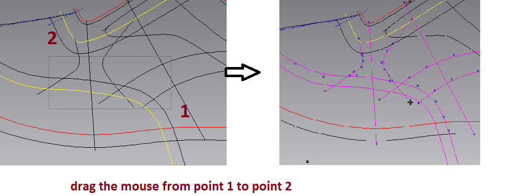
Drag and Drop
- Position the cursor at a point with no entities.
- Holding the Selection key down and drag the cursor to enlarge the selection rectangle.
- All the entities included in the defined rectangle will be selected.
Delete
- This function allows deleting an entity.
- Finally, Select the entity to delete;
- Click with the menu key and select the function Delete or press the Delete button on the keyboard.
Move and rotate function:
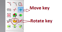
- This function allows us to move, rotate and translate the entities according to its original position. There are two functions to carry out this procedure:
- Select the lines with the selection key, if necessary use the multiple selections;
- Click the icon Move or select it from the menu key;
- Move the cursor towards the required position. During the transfer, it is also possible to rotate the selected entity using the F9 key (45° anticlockwise), F11 (2° anticlockwise) and F12 (2° clockwise).
- The moving coordinates of the selection center (expressed in millimeters) are displayed on the status toolbar as well as the rotation grades of the included entities.
- The entities are moved in real time.
- Confirm the modification with a click on the selection key.
Measure
This function allows measuring the distance between two points, the full length of a line or part of it.
Click on Measure Icon or select the function Utility/Measure.
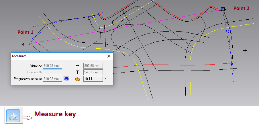
To measure a distance
- Indicate the first point with a click on the selection key;
- The “Measure” dialog box automatically appears showing the information related to the measurement.
- o Move the mouse to the required point.
- The information about the measure is updated in real time while moving the cursor on the entities and is reported in the Distance box.
- The initial and final points used by the function are represented by two references that remain visible until the function is abandoned.
- Confirm with a click;
- Quit the function with the special key or press the Enter key.
Copy/Paste
The function Copy allows to store in the clipboard a copy of the selected entities. The function Paste allows duplicating such entities.
- Select the involved entities eventually making multiple selections;
- Click with the menu key and select Copy or use the combination keys Ctrl + C.
- The duplicated entities can be perfectly overlapped to the previously selected ones or can be directly moved towards the required point.
Zoom Functions
Extended
This function allows for positioning the complete design centrally in order to occupy the whole drawing area. Click on the Zoom icon or press F6.
Pan
This function allows moving the entities displayed in the current working area always keeping the same zoom. Hold the mouse wheel down (the cursor assumes a new shape ) and move the view to the required point.
To cancel an operation (Undo)
This function allows canceling the last 100 operations carried out on the project after the last storage. It is, however, possible to set the highest number of levels.
- Click the icon Undo, or use the combination keys Ctrl + Z;
- Repeat the same procedure for each operation to cancel.
To repeat an operation (Redo)
This function allows for restoring the last canceled operations using the Undo function.
- Click the icon Redo, or use the combination of keys Ctrl + Y;
- Repeat the same procedure for each canceled operation to restore.
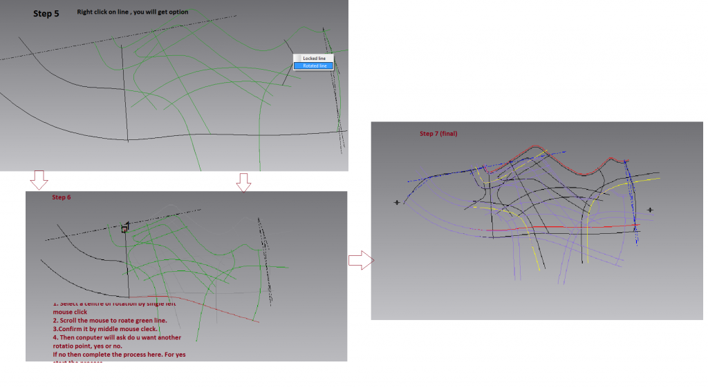
Springing
Since this function can only be applied on “Model pattern” type objects, it is necessary to set the model pattern current.
1. Select the function from 2D/Springing or click on Springing icon.
2. Select all the lines that are to be included in the springing operation: the lines to rotate, the symmetry axis and the lines to be used as a reference (only original lines can be selected).
The symmetry axis must be selected in order to check if the rotation is done well or if it is necessary to use a new rotation center.
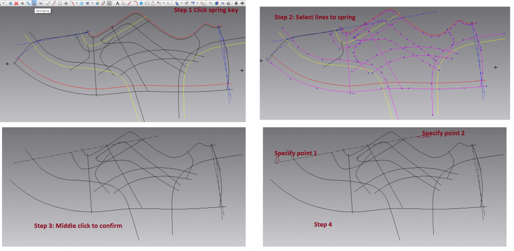
3. Quit the selection with the special key.
In the drawing area only the selected lines will be displayed.
4. If you decide to check the length variation of a line during the springing, select and indicate the initial and the final point of the line section to check, otherwise click the special key.
5. On each line the area to rotate, that to block and eventually the area which will be deformed must be determined.
These three types are represented by the following colours:
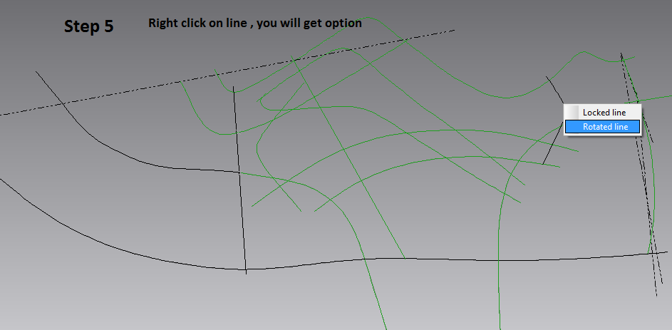
- Locked line – BLACK color
- Rotated line – GREEN color
- Deformed line – RED color
- To speed up the procedure, click the line to spring on the point to start the rotation
- The line directly acquires the sequence of colors: a portion has the black color, the opposite side has the green while the middle portion has the red color.
- The appearing cross can be moved along the line by moving the cursor. If you move the cross towards the locked part the portion to rotate will be increased.
- If you move the cross towards the part to rotate this will be reduced while the section to be deformed will be increased. Always confirm the result with a click of the selection key.
- To reverse the part to rotate, click the menu key and select Reverse.
- To lock the whole line or to rotate it all, select it and choose the required function with a click on the menu key.
- After defining the line, to increase the section to lock (or to rotate) it is enough to click on the involved part and move the cursor along the line towards the required direction. Always confirm the result with a click of the selection key.
6. Quit with the special key and insert the rotation centre.
7. To rotate the lines use the F11 and F12 keys or the mouse wheel.
To spring the lines it could be
necessary to carry out more rotations using different rotations centres. At each rotation the lines must be rotated until the required
point matches the axis. During the rotation it is also possible
to transfer the entities by using the four arrows on the
keyboard to move forward / backward / up /
down.
If a reference line for the length has been chosen at the beginning (point 4) during the rotation you can check the deformation it is undergoing.
The status toolbar, on the first value, shows the initial length of the reference line, on the second value the lengthening millimeters during the current variation. In case of more rotations it also shows the value in millimeters of the overall rotations.
8. To quit the rotation press the special key.
9. If another rotation is required click “Yes” and repeat the operations from point 5, otherwise click “No”.
10. In the drawing area you can see the model pattern with the new lines obtained from the springing represented by a different colour.
Notes
You can quit the springing function with Esc.
Mirror
This function allows reflecting the selected entities according to an axis or to a broken line.
This function is useful after the springing in order to check how the rotated lines match the axis and eventually adjust them before extracting the related piece.
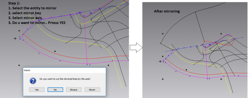
- 1. Select the entities to mirror.
- 2. Click the menu key and select Mirror / with the axis or click the icon on the Mirror
- 3. Indicate the axis or the broken line to use as a reference.
- The entities automatically appear mirrored.
- Like in the example, the entities are mirrored according to the symmetry axis, they are parametrical; if they are mirrored according to a broken line, they remain original.
- An original entity is an entity that does not depend on another entity. An example of an original entity is a line inserted during the digitization.
- A derived entity is an entity obtained transforming another entity. A derived entity depends on the entity from which it derives.
- To edit a derived entity you must go back to the entity from which it depends: this dependence among entities is called Parametricity.
- 5. To check the intersection point with the mirrored line (as in the example) it is advisable to zoom in the involved area.
- When a rotated line is modified the mirrored line automatically undergoes the same modification.
- In the same way, editing the used axis, the position of the derived lines will be automatically updated.
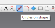
Eyeleting:
- Click circles on shape as shown below
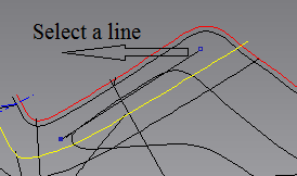
2. Select a line where you want eyelets
3. Select a point then enter distance (0 for same line). Then press enter.
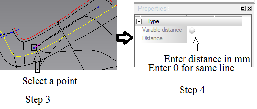
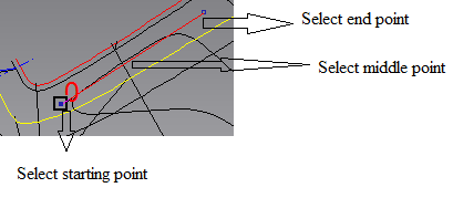
4. Select start point, then end point and then middle point of the line as per picture given below.
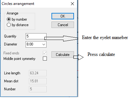
5. Then new windows will come, there you enter eyelet number and eyelet diameter and then press the calculate button as shown in the picture.
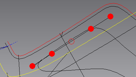
6. Now the Eyeleting is done as shown in picture.
In the next tutorials we will discuss the pattern making.
Reference: Teseo Naxos lessons .. TESEO spa 2011
Please share your feedback and suggestions. In case if you have any queries about any topic of Footwear and Leather Goods, post it in the comment section. And if you like this topic you may share it on facebook, twitter or any social site. Thank you.